Lithium-ion batteries are foundational to the global transition toward electrification, powering everything from smartphones and electric vehicles (EVs) to grid-scale energy storage systems. However, safety and longevity remain persistent challenges; one key limitation is the performance of the solid electrolyte interphase (SEI) layer. At RoCo®, we focus on ionic liquids and advanced electrolyte additives and materials engineered to address these critical pain points.
The SEI Layer: A Crucial Performance Limiter: The SEI layer, typically 10–50 nm thick, forms during the first few charge cycles and is a protective barrier on the anode. A well-formed SEI must exhibit low ionic resistivity (<10 Ω·cm²), elasticity to withstand anode volume changes, and chemical stability to prevent electrolyte decomposition. Failures in SEI performance are linked to lithium dendrite growth, capacity fades (10–20% over 500 cycles), and thermal runaway beyond 100°C.
Advanced Additive Chemistry: RoCo® has developed an ionic liquid SEI additive, a vinyl triazolium-based electro-polymerizable ionic liquid. It offers an electrochemical window of 0–5 V and a bulk ionic conductivity of ~10⁻³ S/cm. It is non-flammable and forms a high-quality SEI layer with no detectable flash point, addressing multiple safety and performance concerns. When combined with vinylene carbonate (VC), which polymerizes at low voltages, the resulting SEI shows a 30% impedance reduction measured via cyclic voltammetry (CV) over 10 cycles at a 1 mV/s scan rate. (See Triazolium Products).
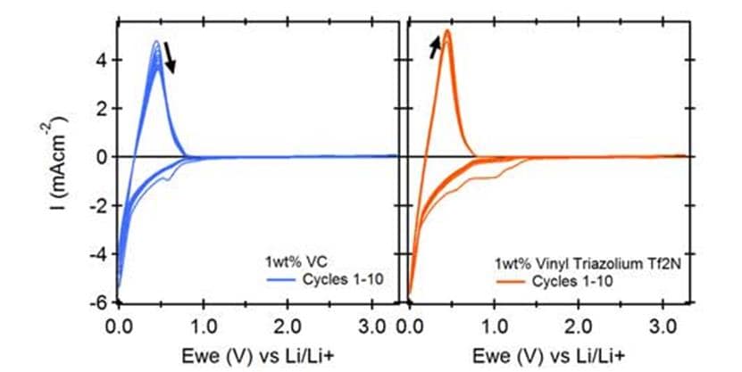 As shown in Figure 1, the experimental data collected under the following conditions—a 2-hour soak at open-circuit voltage (OCV), lithium wire used as both reference and counter electrodes, and a graphite working electrode scanned at 1 mV/s over 10 cycles—demonstrate the superior performance of RoCo®‘s TzVmO2FS. Compared to vinylene carbonate (VC) and fluorinated VC (VC-F), the vinyl triazolium system exhibited lower reductive current and narrower hysteresis in cyclic voltammetry, indicating more efficient and stable SEI formation.
Broader Electrochemical Solutions RoCo® offers a suite of electrolyte and additive solutions:
- Ionic liquid-based electrolytes (e.g., imidazolium, pyrrolidinium salts) deliver 10–15 mS/cm conductivity at 25°C and stability up to 4.5 V coupled with traditional carbonate solvents.
- Solid-state battery polymers, including Polydiallyldimethylpyrrolidinium-based systems, provide >20 MPa tensile strength and high ionic transport available in FSI and TFSI anions.
- High-purity lithium salts (>99.9%) such as LiPF₆, Li-FSI, and Li-TFSI enhance SEI stability and system energy density (target >300 Wh/kg).
Multifunctional Role of Additives RoCo® has designed multifunctional additives that serve essential roles in commercial and research battery systems:
- SEI Formers: Reduce initial capacity loss (<5%) and increase Coulombic efficiency (>99.5%).
- Cathode Protection Agents: Prevent oxidative decomposition at high voltages.
- Salt Stabilizers: Suppress decomposition of LiPF₆ into reactive phosphine/fluorine gases.
- Fire Retardants & Overcharge Protectors: Improve thermal safety by incorporating various ionic liquids into electrolyte chemistry.
- Lithium Deposition Modifiers: Promote uniform Li plating.
- Corrosion Inhibitors: Extend metal component life.
- Solvation Enhancers: Increase ion mobility.
- Wetting Agents/Viscosity Modifiers: Improve electrolyte penetration.
Conclusion RoCo®’s cutting-edge electrolyte additives and materials significantly improve battery performance, safety, and longevity. Through innovations like vinyl triazolium and complementary solutions, we support the transition to safer, higher-performance lithium-ion and solid-state batteries. Contact RoCo® for custom materials and technical consultation to optimize your next-generation energy storage applications.