Authors: Dan Soeder, Hunaid Nulwala, James Lawler, Daryl-Lynn Roberts
Team Carbon Blade is pioneering carbon capture and storage solution that provides stand-alone, small-footprint “Blade” (Direct Air Capture (DAC)) modules that combine wind-powered electrodialysis with bipolar membrane separation (EDBM) to remove CO2 from ambient air at less than $100/t CO2. The small footprint units can be deployed wherever underground or other CO2 storage or transport options exist, enabling a scalable solution.
Team Carbon Blade is a registered participant in the Elon Musk X-Prize carbon removal competition and comprises experts from all key disciplines relevant to developing and implementing a scalable solution to carbon capture and storage. These include advanced materials chemistry and physics, fluid dynamics, computational mechanics, energy technology commercialization, and geologic storage. Team bios are at the end of this article.
The CO2 bathtub is overflowing, and experts believe that drastic measures are necessary.
Continuous measurements of atmospheric carbon dioxide (CO2) began in 1957 on the flank of the Mauna Loa volcano in Hawaii at a trace gas observatory established by the U.S. National Oceanic and Atmospheric Administration (NOAA) and operated by the Scripps Institute of Oceanography. In 1976 a group from Scripps and NOAA decided to analyze trends in the measurements for any variations (Keeling et al., 1976). Figure 1 shows what is known as the “Keeling Curve” after this 1976 publication. This curve shows the CO2 concentration increase in parts per million in the atmosphere over time. These measurements have continued to the present day at about 160 stations across the globe.
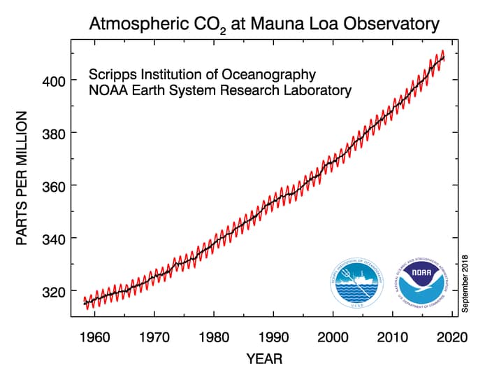
Figure 1: The Keeling Curve of carbon dioxide levels in the atmosphere measured since 1957 at Mauna Loa in Hawaii. The sawtooth pattern represents seasonal changes in CO2 as northern hemisphere plants bloom in spring and go dormant in fall. The solid line up the center is the annual average trend.
Source: U.S. National Oceanic and Atmospheric Administration (NOAA) public domain
The Keeling Curve shows a steady increase in the concentration of CO2 in the atmosphere of nearly 100 parts per million (ppm) over the past 60 years. The sawtooth line represents the annual cycle of vegetation blooming in spring and absorbing CO2, then going dormant in the fall and ultimately returning the CO2 to the atmosphere. The solid, dark line located in the center is the average annual concentration trend. It is important to note that the average yearly concentration line is steepening with time.
What is causing this increasing concentration of atmospheric CO2? Some have suggested that natural sources such as volcanic eruptions might be responsible. Although volcanic eruptions may emit copious quantities of CO2 into the atmosphere, many large eruptions would be necessary to account for the upward slope. There is no evidence that any sustained mega-eruptions have occurred within this time frame. Most volcanoes erupt episodically, which would result in irregular, upward spikes on the Keeling Curve. Yet, it shows a relatively smooth and steady increase in average CO2 levels over time. Other proposed sources of GHG like forest fires, rotting vegetation, and even cattle flatulence would not produce the rapid anomaly shown in the Keeling Curve. In a balanced carbon cycle, carbon flows between Earth’s natural reservoirs – the ocean, soils, and vegetation – without rapid accumulation in the atmosphere.
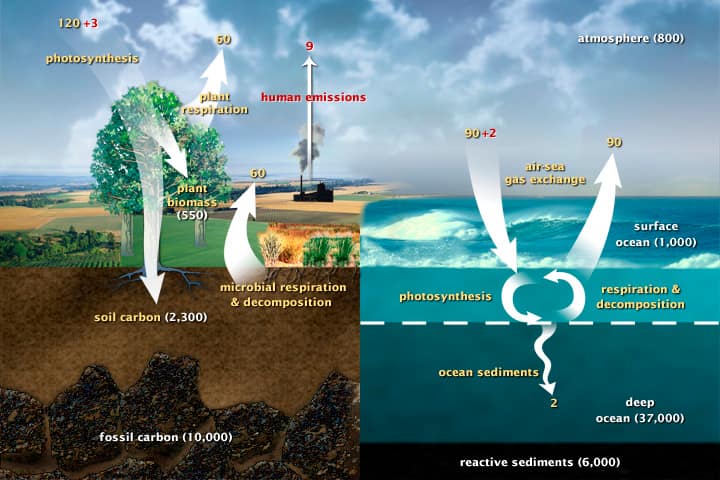
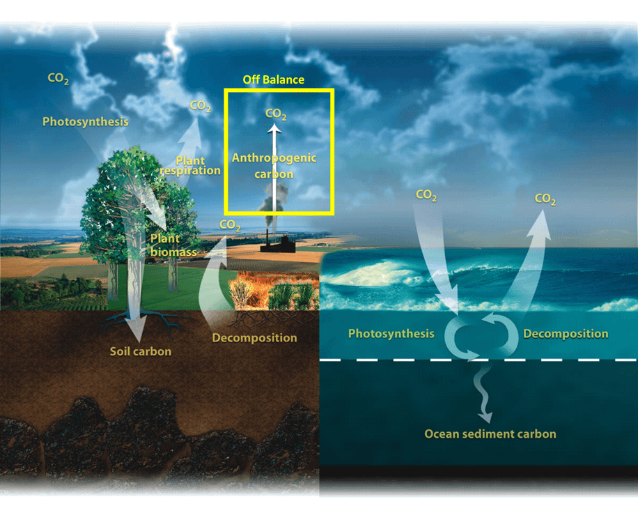
Figure 2: The diagram shows the overall carbon cycle leading to the movement of carbon between land, atmosphere, and oceans. Yellow numbers are natural fluxes, and red is human contributions in gigatons of carbon per year. White numbers indicate stored carbon.
Source: “The Carbon Cycle.” Earth Observatory. NASA
However, burning fossil fuels such as coal, petroleum, and natural gas releases excess carbon that had been stored deep underground for millions of years. This carbon is not part of the atmospheric carbon cycle (Figure 2), and so once released, that process cannot fully reabsorb it. The trend of increased fossil fuel use since the Industrial Revolution (Figure 3) matches the increased CO2 concentrations in the atmosphere shown in Figure 1. These trends precisely explain the Keeling Curve anomaly.
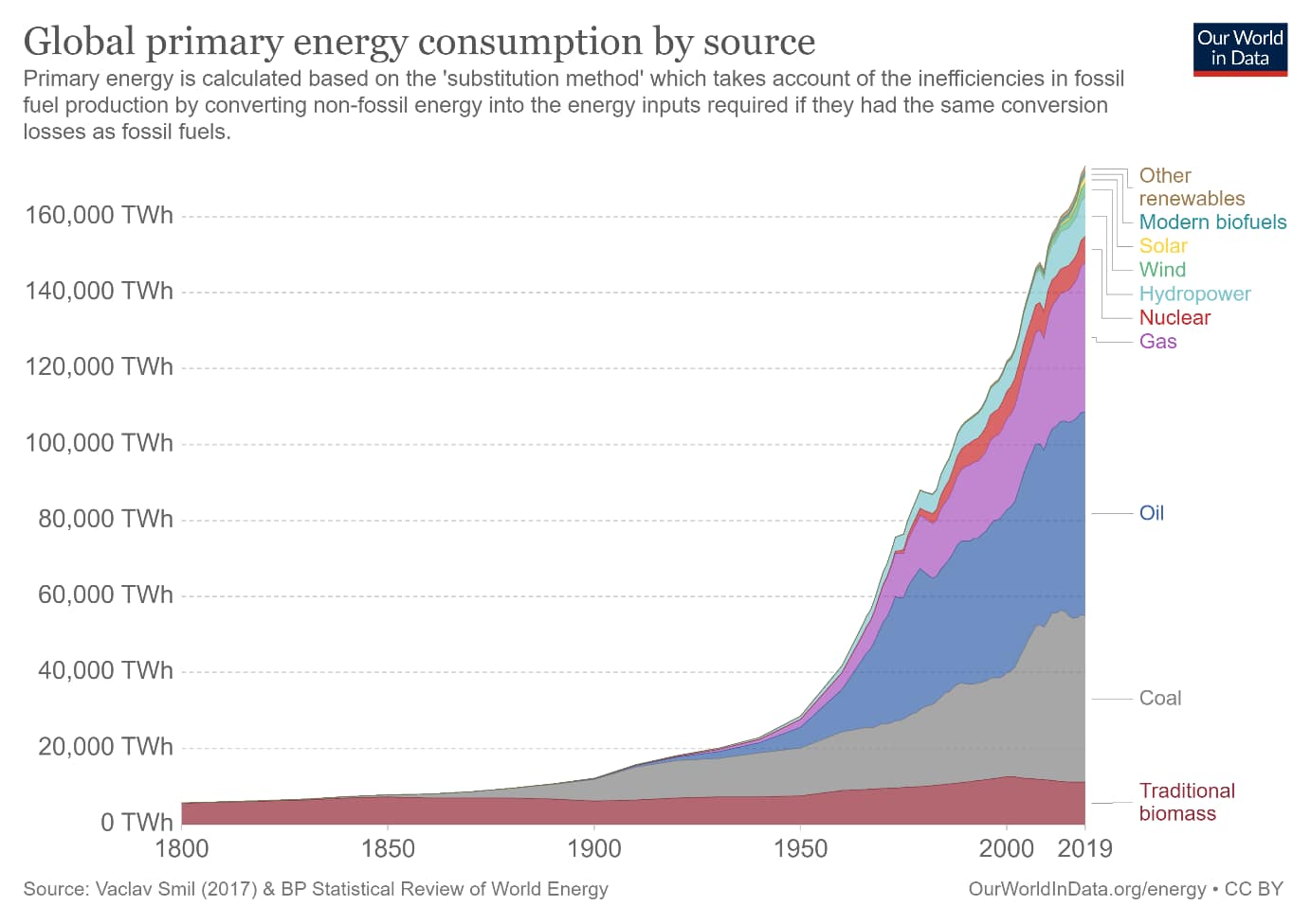
Figure 3: Global energy consumption from 1800 to 2019, showing the dominance of fossil fuels.
Source: Ritchie, H. “Energy” (open access) Published online at OurWorldInData.org.
CO2 is known as a “greenhouse gas” (GHG) because it absorbs infrared (heat) radiation. Specifically, higher concentrations of CO2 in the air absorb more heat and result in a warmer atmosphere. Since the early part of the 19th century, it has been acknowledged that shortwave infrared (I.R.) radiation from the sun penetrates the atmosphere and warms the Earth. The warm Earth, in turn, radiates heat back into space as longer wavelength I.R. CO2 and other GHGs absorb the longer I.R. wavelengths, warming the air from below. This is why air temperature decreases with altitude, and high mountain peaks are perpetually snow-covered.
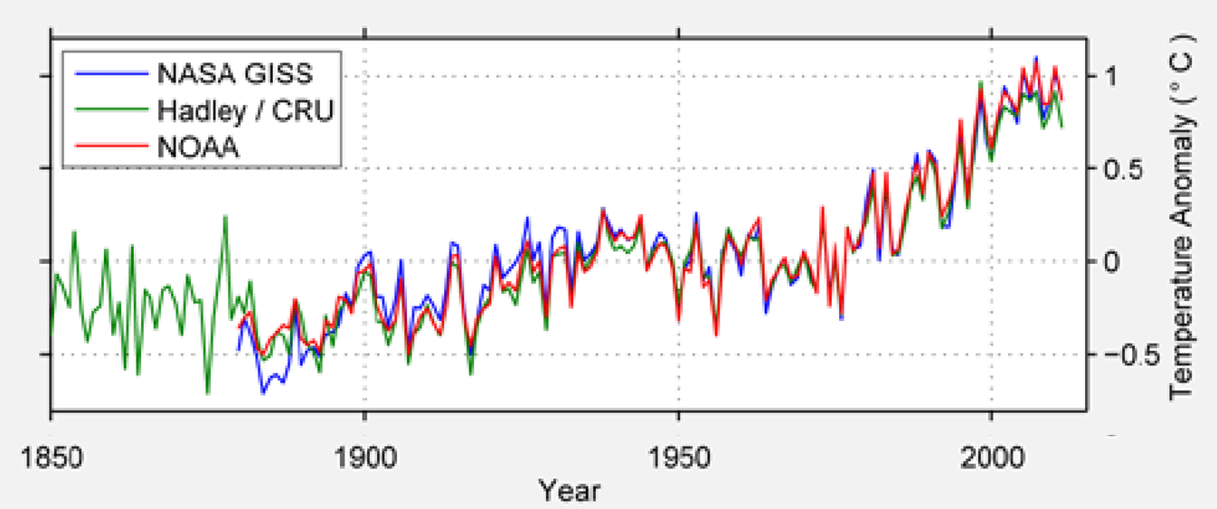 Mathematical climate models are complex simulations that represent the interactions of significant climate components (atmosphere, land surface, ocean, and sea ice), with a specific focus on Earth’s energy balance. These models predict that a warmer atmosphere leads to unstable climates by melting polar ice caps, altering ocean currents, and rising sea levels. Warm air holds more water vapor than cold air; thus, a warmer climate will result in more intense droughts along with more intense storms. Climate change is already occurring, as is evident in the climate data (Figure 4). Based on multiple sources of evidence, human-produced or “anthropogenic” GHG is the leading cause of climate change. An excellent resource to learn about climate change and GHG is the American Chemical Society’s climate toolkit.
Figure 4: change in temperature over time from different sources. Note that temperature has gone up from the 1960s and compared it to the data in Figure 1.
Source: (Muller 2013)
For the last century, human civilization and progress have thrived from readily available fossil fuels. Most electricity is generated by burning fossil fuels, and most vehicles run on liquid fuels like gasoline or diesel. Coal and natural gas are used directly in industrial processes ranging from steelmaking to cement manufacturing. Despite a significant push towards renewable energy (wind turbines and solar) and a sixty-year history of nuclear power deployment, the United States still obtains 80 percent of its primary energy from fossil fuels with the largest economy globally. The second-largest economy, China, obtains 86 percent of its energy from fossil fuels. Replacing these fuels with energy resources that emit zero GHG is an enormous challenge.
Addressing climate change is a complex problem and will require the incorporation of multiple solutions. The Intergovernmental Panel on Climate Change (IPCC) Special Report on Global Warming of 1.5 Degrees states that global emissions of GHGs must reach net-zero by 2050 to limit warming to 1.5 degrees C. This will mean switching to carbon-neutral or carbon-free energy sources, reducing CO2 emissions from other industrial processes, developing carbon-neutral or CO2 negative materials, and removing CO2 directly from the atmosphere.
Compared to the 34 billion metric tons of anthropogenic CO2 released globally to the atmosphere in 2020, the annual amount of CO2 captured and stored by all of humanity was only roughly 5 million metric tons in 2020. There are several ways by which this is currently accomplished. The CO2 generated from prominent industrial sources, such as power plants, can be captured at the source and stored/isolated from the atmosphere. This process is known as carbon capture and storage or CCS. CCS has not been implemented widely as the process is expensive. Still, the economics can be improved if a profitable use can be found for the captured CO2 (referred to as CCUS, for carbon capture “utilization” and storage). Ambient atmospheric GHG levels can be reduced by removing CO2 directly from the air with direct air capture or DAC (Kramer, 2018). DAC can be achieved biologically by planting trees or growing algae or mechanically by the chemical removal of CO2. Carbon dioxide captured by mechanical DAC must be stored similarly to CCS.
Current designs to capture CO2 at the source point (CCS) are bulky and limited to stationary sources of carbon dioxide, such as power plants. The two primary existing processes for separating CO2 from flue gases are chemical or cryogenic, although membrane separation may yield another potential approach (Songolzadeh et al., 2014). Chemical methods use amines to absorb carbon dioxide directly from the flue gas and release it elsewhere for storage by changing the pressure or temperature. The cryogenic process works by freezing the CO2 out of the air, converting it to solid “dry ice” at very cold temperatures (-109.3 °F or -78.5 °C). Neither approach is energy efficient– the energy cost for carbon capture is 15 percent or more of a power plant’s output and does not account for the cost associated with sequestration and transport.
Carbon dioxide at the moment has low commercial value, limiting the potential for utilization in CCUS. Industries that utilize the gas harvest it directly from CO2 wells in naturally occurring underground reservoirs at the cost of $30 to $40 per ton (Kramer, 2018). Depending on the method deployed, capturing carbon dioxide from flue gases costs about $100 to $200 per ton. This price disparity has hobbled CCUS. Currently, the primary use for captured CO2 is to re-pressurize depleted petroleum reservoirs for enhanced oil recovery (EOR) operations. EOR is done primarily because the CO2 is available for oilfield operations and receives a tax credit since the CO2 remains sequestered underground. However, more petroleum to be burned may offset any net carbon storage and does not help with the climate crisis at hand.
Another concern with the “utilization” component of CCUS is the challenge of transporting the captured carbon dioxide from the source to the use location. If a power plant is near an enhanced oil recovery area, then seamless transport can be achieved. For example, Petra Nova Project (CCUS) captures about 90 percent of the CO2 emissions from a coal-fired powerplant near Houston, Texas. It transports the gas via pipeline to Hilcorp’s West Ranch oil field, located near Vanderbilt, Texas, in EOR operations. Project plans call for the eventual sequestration of some 1.4 million metric tons of CO2 annually.
In contrast, direct air capture (DAC) systems have the potential advantage of removing CO2 directly from the atmosphere with no restriction to a specific CO2 source. A DAC system can be placed in an area with favorable geologic features for carbon storage, eliminating the need for dedicated transport pipelines.
The three main storage options for CO2 are 1) geologic storage deep underground, 2) terrestrial storage in soils, vegetation, or manufactured materials on the surface, and 3) ocean storage in deep seawater (Ajayi et al., 2019).
Geologic storage seeks to place CO2 deep underground to keep it isolated and stored for the long term. It is done by compressing CO2 into deep rocks. At elevated pressures, carbon dioxide forms what is known as a “supercritical fluid,” where the compressed gas transforms into a high-density liquid. The so-called “critical point” where this occurs for CO2 is 88 degrees F at 1070 psi (31 degrees C at 7.38 MPa). In rock formations under normal hydrostatic pressure gradients, the transformation occurs at depths of about 2,500 feet (800 m). At this point, a small increase in pressure will cause a significant increase in the density of the supercritical fluid. Thus, substantially more CO2 can be stored in rock formations as a supercritical fluid than gas. Depending on the geologic storage option under consideration, this can be important.
The most popular geologic storage options include the following:
- Depleted conventional oil and gas fields: These held oil and natural gas underground over extended periods in porous rocks sealed within a geologic trap like a fold or an offset along a fault. If the integrity of the trap was not compromised during oilfield operations, the depleted field contains empty pore space that could potentially store CO2. Depleted fields have existing wells that can be used for injection, and the injected CO2 can often be used to recover additional oil from the reservoir. This has been done on old oilfields in Texas, Louisiana, and Wyoming. The economics require relatively high oil prices. However, there is a concern that the stored CO2 might leak out of the geologic reservoir and migrate back to the surface. Potential flow paths to the surface include a possible breach in the caprock from pressure cycling during oil production and leaks created by the deterioration of the materials used to construct wells, such as steel casing and downhole cement (Watson and Bachu, 2009).
- Coal seams: The organic carbon that makes up the bulk of coal can adsorb or chemically attach itself to CO2, providing a significant amount of storage estimated to store 85-100 Gt of CO2. Coal seams that have not been mined because they are too deep or too thin are potential candidates for CO2 storage. Coal seam storage of CO2 has been investigated in the laboratory, but no large-scale field tests have been conducted.
- Depleted gas shales: Organic-rich shales that have been hydraulically fractured (“fracked”) to produce natural gas may provide another option for CO2 storage once they are depleted (Levine et al., 2016). Like conventional oil and gas reservoirs, depleted shales would have existing wells and empty pore space for CO2, and like coal, the organic-rich shale would also adsorb a component of the gas. However, it is unclear when production companies would declare a shale gas well “depleted.” These are known to produce slow but steady amounts of natural gas for decades. In addition, the possible effects of fracking on the integrity of shale for CO2 storage are unknown. There have been laboratory experiments, but the shale gas industry vehemently opposes any field tests of CO2 injection into gas shales.
- Deep saline aquifers: Porous rocks at great depths contain very salty water rather than the fresh groundwater obtained near the surface. This saltwater can hold CO2 in solution under high pressure. Dissolved CO2 requires less subsurface pore volume than gaseous or even supercritical CO2 to store the same amount. The downside is that drilling to the depths of these saltwater aquifers is expensive. Also, carbon dioxide forms a weak acid when dissolved in water, and the potential effects on wells and the rock formation itself are unclear.
- Basaltic lava rocks: These rocks weather easily and release calcium and magnesium into a solution that reacts chemically with the CO2 and turns it into the solid carbonate minerals calcite and magnesite. A significant advantage of the mineralization process is that once converted, and the CO2 is essentially fixed. Basalts contain the correct minerals for providing Ca and Mg, but they are often highly fractured, and it is not clear how well the CO2 will be contained within the rock while undergoing the conversion to mineral form. However, the required residence time appears relatively short; field experiments in Iceland found that CO2 injected into basalt formed carbonates in as little as two years (Matter et al., 2016).
Terrestrial storage of CO2 seeks to store the gas in soils or vegetation or utilize CO2 in construction materials to keep it out of the atmosphere for an extended period. Storage in terrestrial ecosystems uses soils and biomass in forests to sequester CO2 as organic carbon (Litynski et al., 2006). Another option is to use biofuels to capture the CO2 from the air through plant growth and subsequently apply CCS when the fuel is burned to store the CO2. This is known as biofuel energy carbon capture and storage, or BECCS. Other ideas for terrestrial carbon storage include:
- Concrete manufacturing is a major emitter of GHG, so using it to sequester CO2 can substantially offset these emissions. The material that holds concrete together is cement, made of calcium oxide (CaO) that reacts with CO2 as the concrete cures to form calcite. Several methods have been developed to introduce CO2 into the cement mixture to enhance this reaction, sequester the CO2, and make the concrete stronger. Once locked down in the concrete, the CO2 stays in place for long periods. Sealed greenhouses: Various exotic hardwoods and other desirable plant-based construction materials like bamboo could be grown quickly in greenhouses containing a CO2-enriched atmosphere. It is unclear if this approach can be scaled up to make much of a difference towards climate change.
- Microbial conversion to methane: CO2, provided to cultures of anaerobic bacteria, is converted into methane gas. CO2 from the biomethane combustion could be captured and recycled or permanently sequestered in a BECCS system.
- Microbial conversion of CO2 to valuable materials: Microbes can convert CO2 to calcite or create graphene, carbon fiber, carbon nanotubes, or other desirable materials from CO2.
- Chemical conversion of CO2 to fuels or materials: Chemical engineering technology can convert CO2 into ethylene and other products or feedstock materials that are currently fossil sourced. The economics of these processes remains uncertain.
Ocean storage of CO2 involves injecting carbon dioxide into seawater at depths greater than one kilometer from ships, pipelines, or offshore platforms. The CO2 is supercritical with a density greater than water at these depths and will dissolve and disperse without coming to the surface (Herzog et al., 2000). However, given the concerns about ocean acidification by CO2 inputs from the atmosphere, major environmental impacts could be on deep-sea biota near concentrated CO2 injection points (Seibel and Walsh, 2003). Ocean storage remains in the research stage without any actual field tests (Ajayi et al., 2019).
The IPCC recommends that at least 10 billion tons of CO2 be removed annually to avoid the worst aspects of climate change (IPCC, 2018). We have released an overabundance of carbon into the atmosphere, and the proverbial bathtub is overflowing. Unfortunately, it will always be more cost-effective to pollute. So widespread and stringent carbon tax policies are necessary to facilitate more favorable economics for CCS, CCUS, and DAC systems, to stimulate further development and deployment. Market-based solutions, such as carbon fee and dividend policies, which distribute proceeds from carbon taxes back to the population, are growth-stimulating and equitable, representing a viable path to accomplishing this goal. The world has reached a point where urgent action in this direction is required to avoid massive economic damage and the further destruction of this priceless planet.